One of the most critical elements of producing any cable assembly is the amount of cable assemblies testing that is done when the product is completed in manufacturing. There are many methods and levels for testing cable assemblies, but all testing has one goal – to ensure that the product meets or exceeds its specifications.
At a bare minimum, cable assembly testing must include complete electrical tests for shorts, opens, or incorrect wiring. The proper method to electrically test an assembly is to attach the connector at each end of the assembly to a mating connector. The mating connector will be attached to a fixture that will check for opens in the assembly, shorts between the conductors or the conductors and shields if any are present, and the proper pin placement for all the components of the assembly. This setup puts the assembly into a test situation that fully replicates the installation that the assembly was built for.
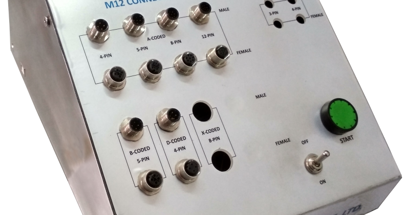
Katlax has recently developed electrical continuity tester for M8 and M12 connector and cable assemblies. This tester is computer based connected through USB cable and shows PASS / FAIL results display on screen, no. of connectors tested…and many features are under development. The whole hardware and software designed and developed in-house.
Features:
- M8, A-coded 3, 4-pin with Male & Female combinations.
- M12, A-coded, 3, 4, 5, 8 & 12-pin with Male female combination.
- M12, B-coded, 5-pin with Male female combination.
- M12, D-coded, 4-pin with Male female combination (Only Continuity)
- M12, X-coded, 8-pin with Male female combination (Only Continuity)
- Display results on screen
- Report generation
Further project is under development for communication and data transfer speed testing in case of D-coded, PROFINET and X-coded Ethernet connector. This tester will have PLCs and HMI for checking communication of category cables for PROFINET and Industrial Ethernet application.
Additional testing may be considered from a visual, environmental, mechanical, and signal integrity standpoint.
