
Pin Assignments & Wire Color Code
TECHNICAL REFERENCE
Pin Assignments & Wire Color Code
Pin-out diagrams and IEC industrial wire colour codes for Katlax signal, data, and power connectors — M8, M12, 7/8", M23 and M40. Reference the tables below when building custom cable assemblies or cross-checking wiring during installation.
Pin Assignments of M8 Signal Connector
Face View
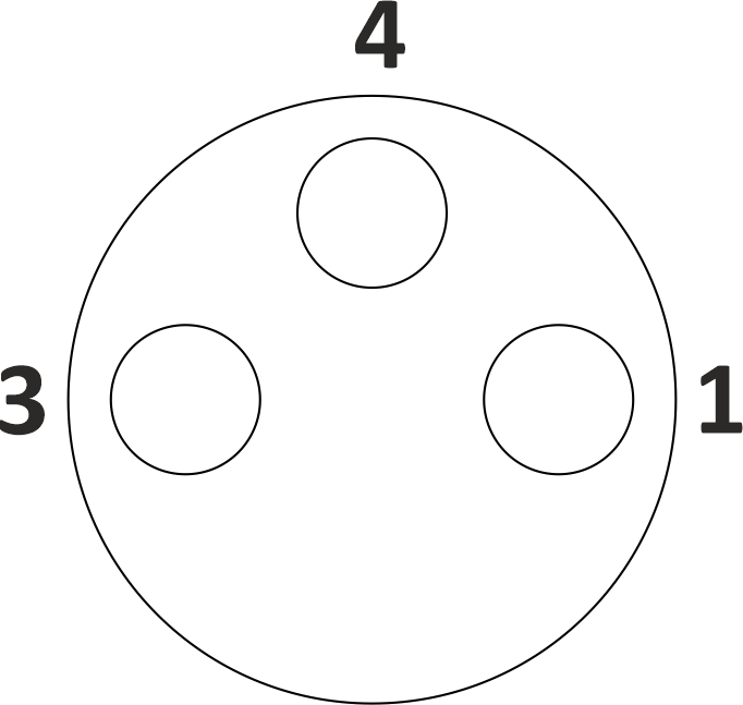
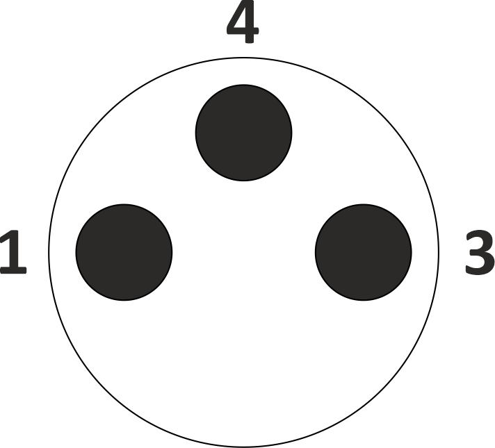
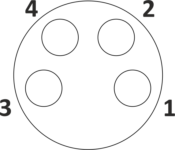
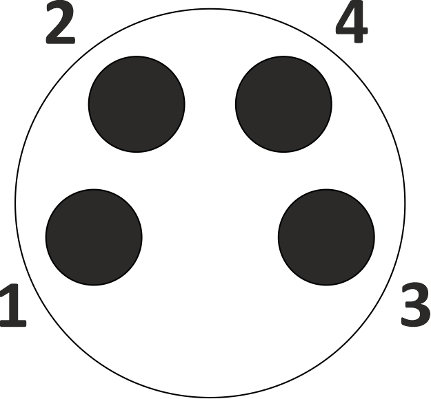
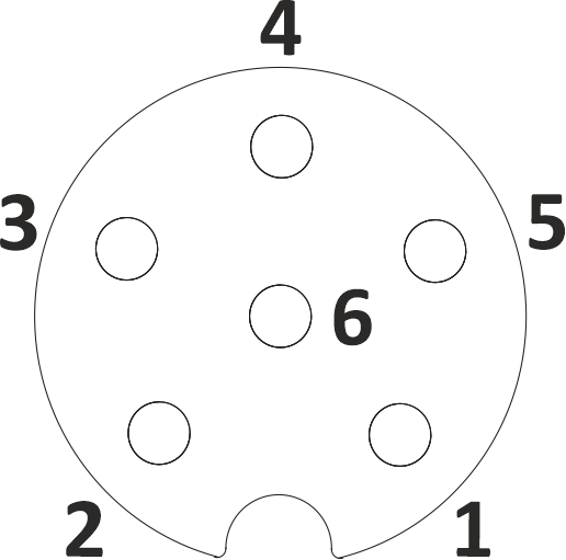
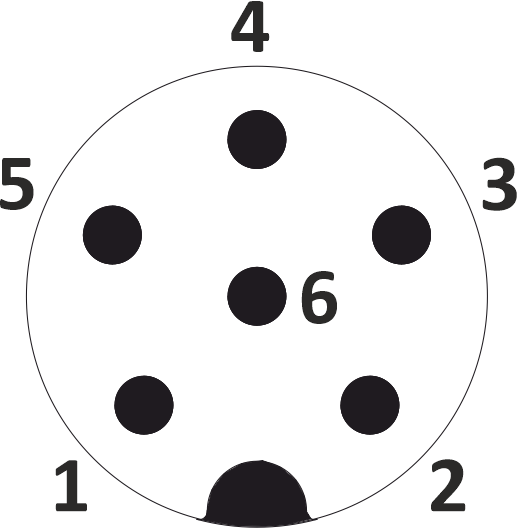
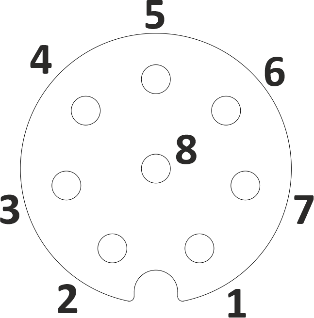
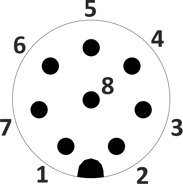
Pin-Out & Wire Colour
| Pin | 3-Pin | 4-Pin | 6-Pin | 8-Pin |
|---|---|---|---|---|
| 1 | BN | BN | BN | WH |
| 2 | — | WH | WH | BN |
| 3 | BU | BU | BU | GN |
| 4 | BK | BK | BK | YE |
| 5 | — | — | GY | GY |
| 6 | — | — | PK | PK |
| 7 | — | — | — | BU |
| 8 | — | — | — | RD |
Face View
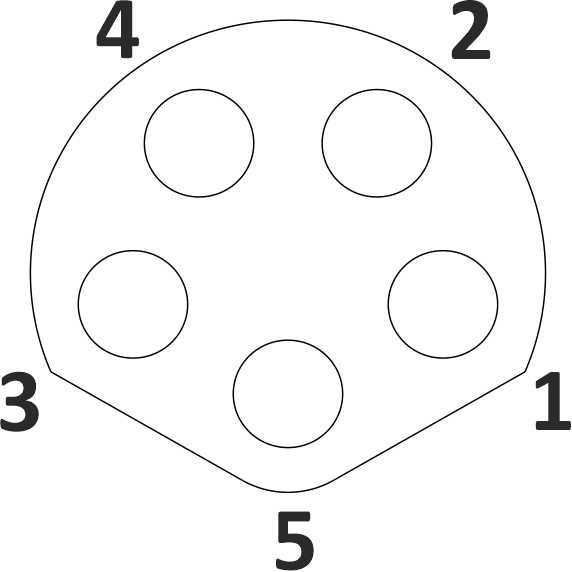
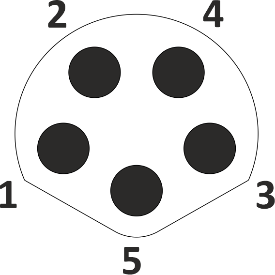
Pin-Out & Wire Colour
| Pin | 5-Pin Male/Female |
|---|---|
| 1 | BN |
| 2 | WH |
| 3 | BU |
| 4 | BK |
| 5 | GY |
Pin Assignments of M8 Data Connector
Face View
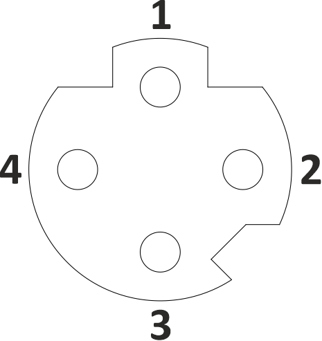
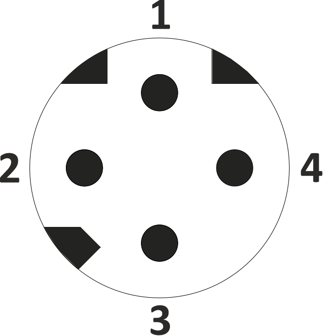
Pin-Out & Wire Colour
| Pin | 4-Pin Male/Female |
|---|---|
| 1 | YE |
| 2 | WH |
| 3 | OR |
| 4 | BU |
Pin Assignments of M12 Signal Connector
Face View
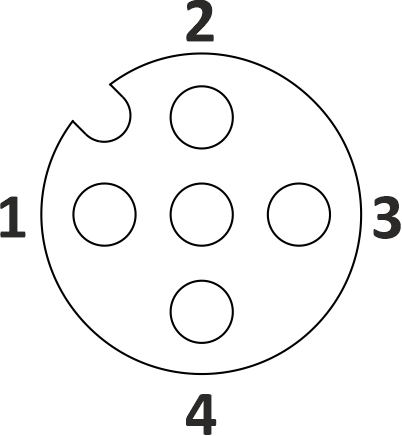
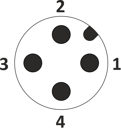
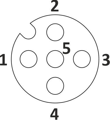
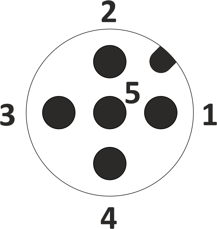
Pin-Out & Wire Colour
| Pin | 3-Pin Male/Female | 4-Pin Male/Female | 5-Pin Male/Female |
|---|---|---|---|
| 1 | BN | BN | BN |
| 2 | — | WH | WH |
| 3 | BU | BU | BU |
| 4 | BK | BK | BK |
| 5 | — | — | GY |
Face View
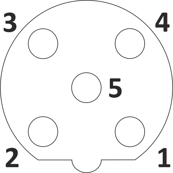
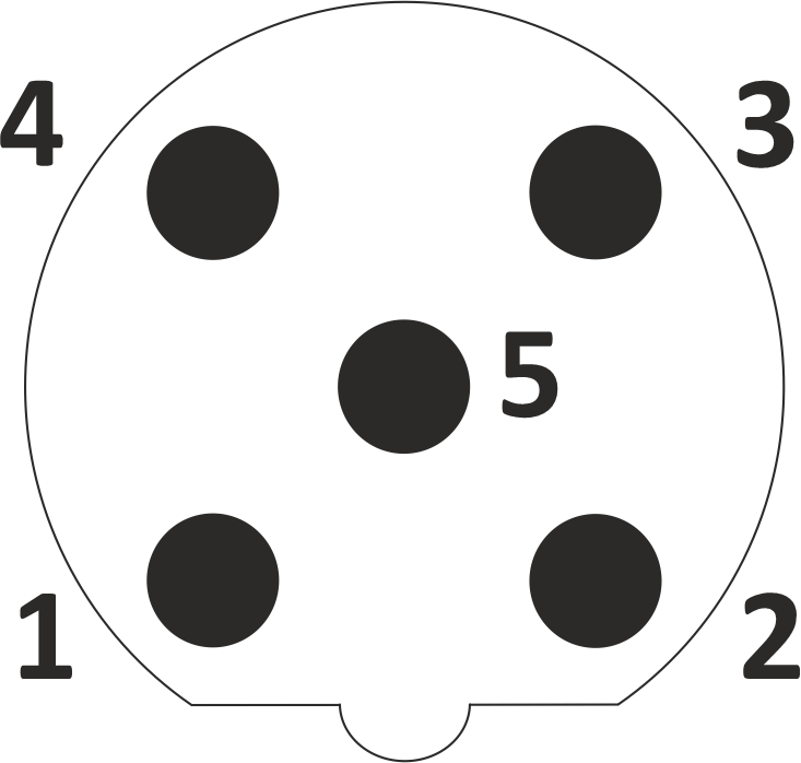
Pin-Out & Wire Colour
| Pin | 5-Pin Male/Female |
|---|---|
| 1 | BN |
| 2 | WH |
| 3 | BU |
| 4 | BK |
| 5 | GY |
Face View
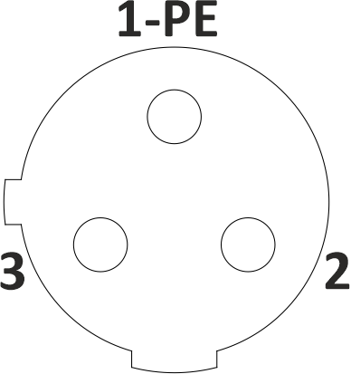
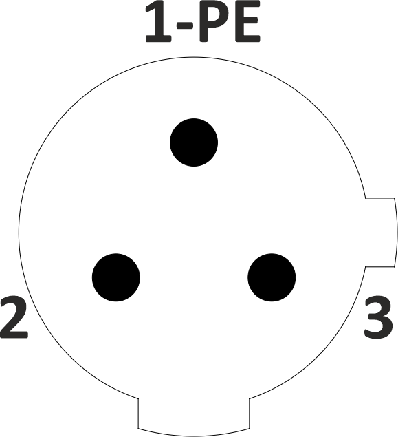
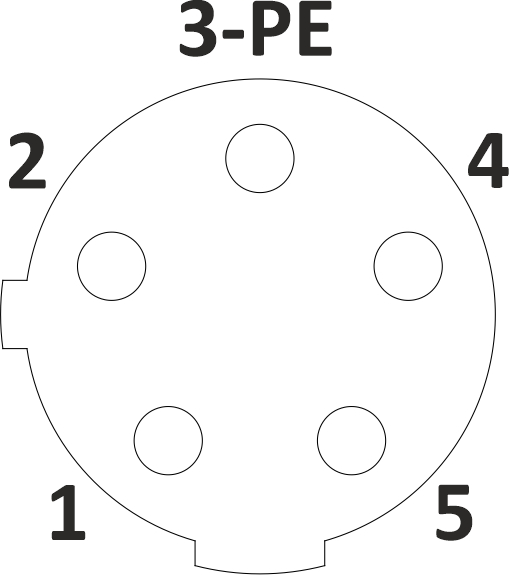
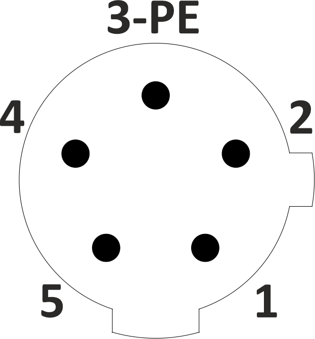
Pin-Out & Wire Colour
| Pin | 3-Pin Male/Female | 5-Pin Male/Female |
|---|---|---|
| 1 | GN/YE | BN |
| 2 | BN | WH |
| 3 | BU | BU |
| 4 | — | BK |
| 5 | — | GY |
Pin 1 in the 3-Pin variant is a protective earth (PE).
Face View
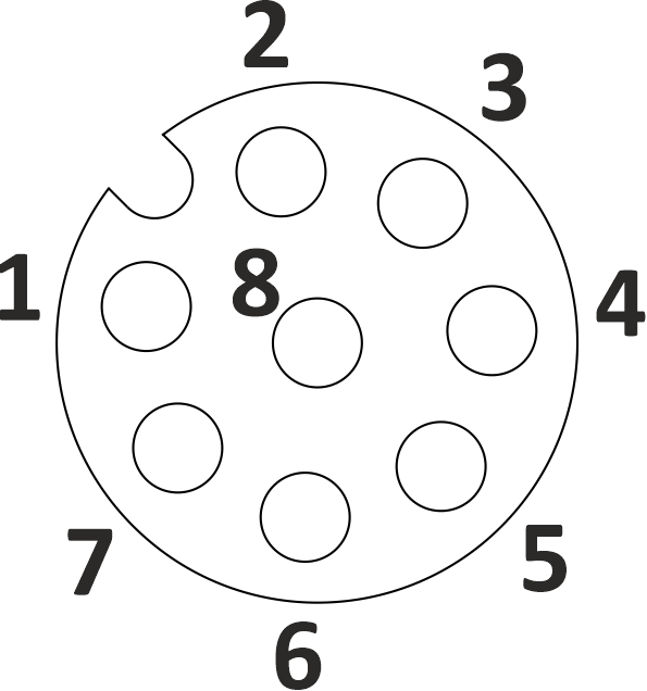
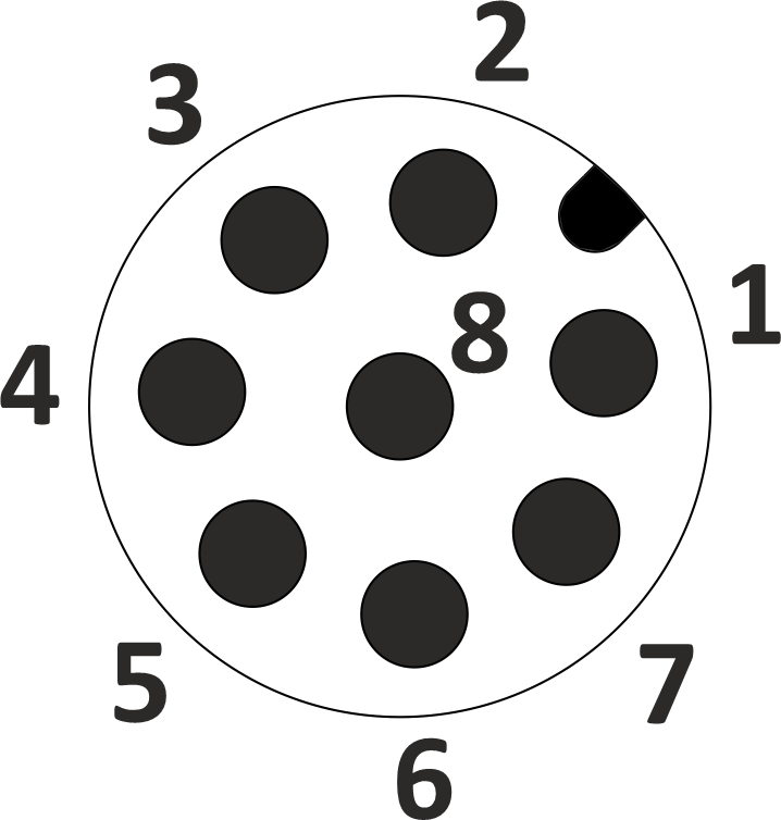
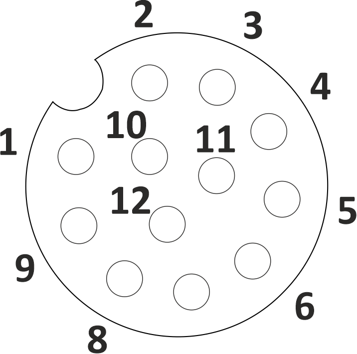
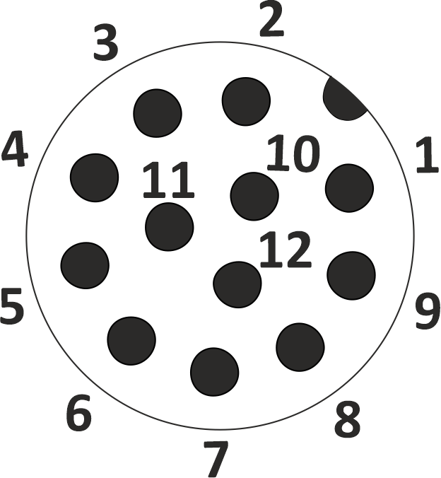
Pin-Out & Wire Colour
| Pin | 8-Pin Male/Female | 12-Pin Male/Female |
|---|---|---|
| 1 | WH | BN |
| 2 | BN | BU |
| 3 | GN | WH |
| 4 | YE | GN |
| 5 | GY | PK |
| 6 | PK | YE |
| 7 | BU | BK |
| 8 | RD | GY |
| 9 | — | RD |
| 10 | — | VT |
| 11 | — | GY/PK |
| 12 | — | RD/BU |
Pin Assignments of M12 Data Connector
Face View
Pin-Out & Wire Colour
| Pin | 4-Pin CC-Link | 5-Pin CANopen |
|---|---|---|
| 1 | SHSH | SHSH |
| 2 | WH | RD |
| 3 | YE | BK |
| 4 | BU | WH |
| 5 | — | BU |
SH = cable shield / drain wire.
Face View
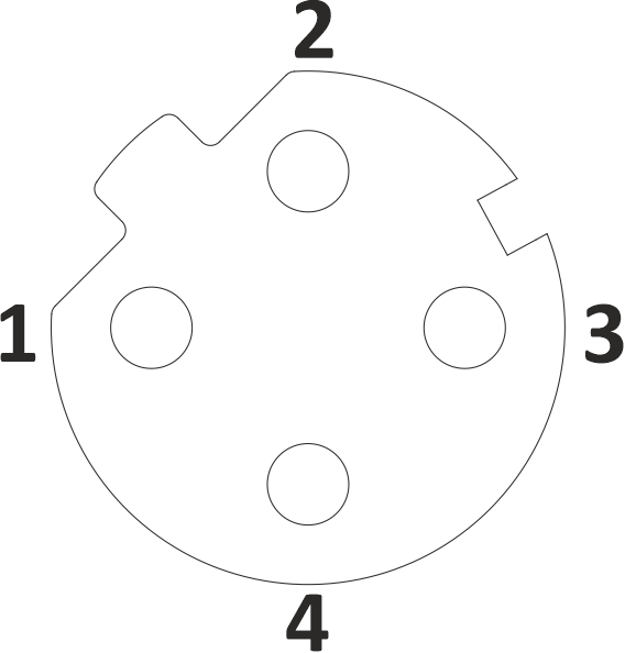
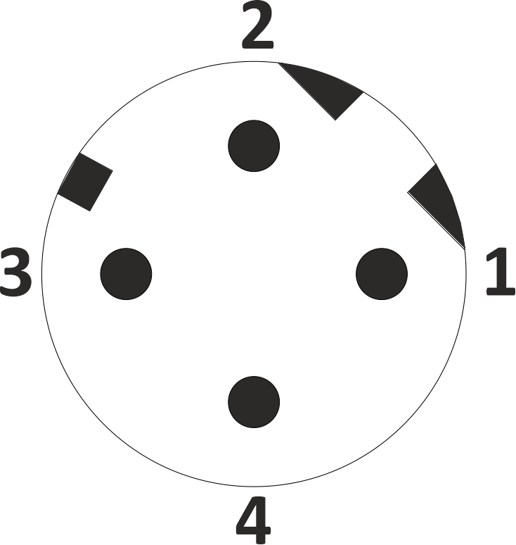
Pin-Out & Wire Colour
| Pin | 4-Pin Male/Female |
|---|---|
| 1 | YE |
| 2 | WH |
| 3 | OR |
| 4 | BU |
Face View
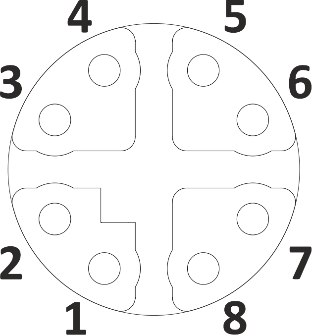
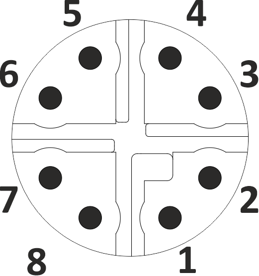
Pin-Out & Wire Colour
| Pin | 8-Pin Male/Female |
|---|---|
| 1 | WH/OR |
| 2 | OR |
| 3 | WH/GN |
| 4 | GN |
| 5 | WH/BN |
| 6 | BN |
| 7 | WH/BU |
| 8 | BU |
Pin Assignments of M12 Power Connector
Face View
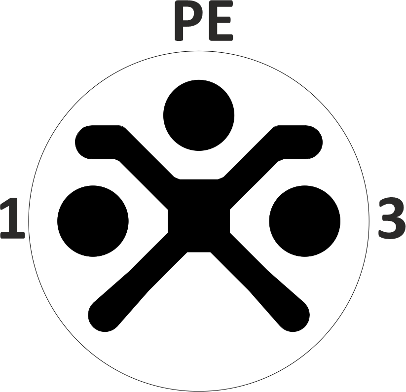
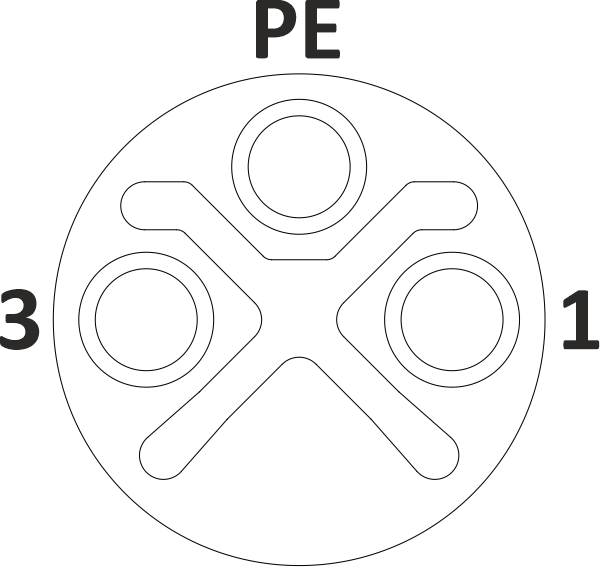
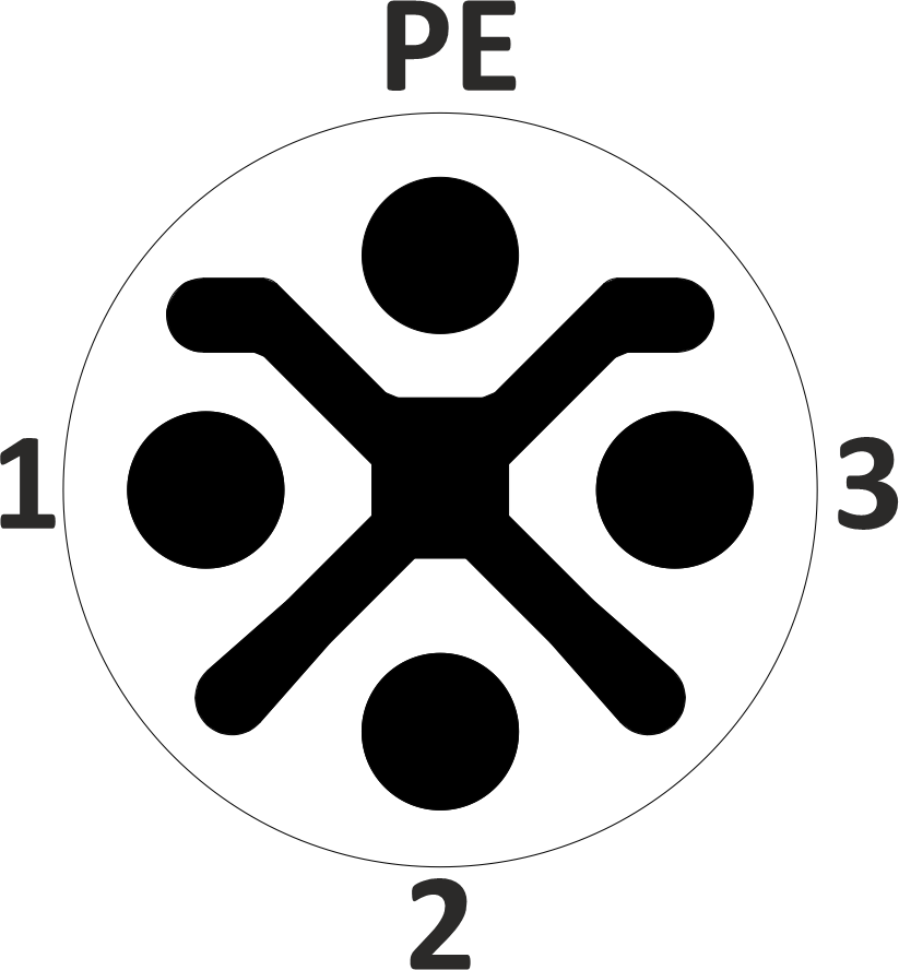
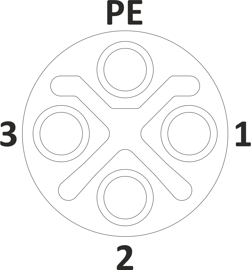
Pin-Out & Wire Colour
| Pin | 2+PE Male/Female | 3+PE Male/Female |
|---|---|---|
| 1 | BK | BK |
| 2 | — | BK |
| 3 | BK | BK |
| PE | GN/YE | GN/YE |
Face View
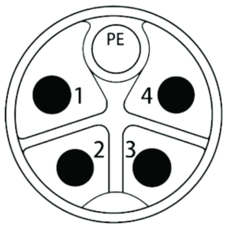
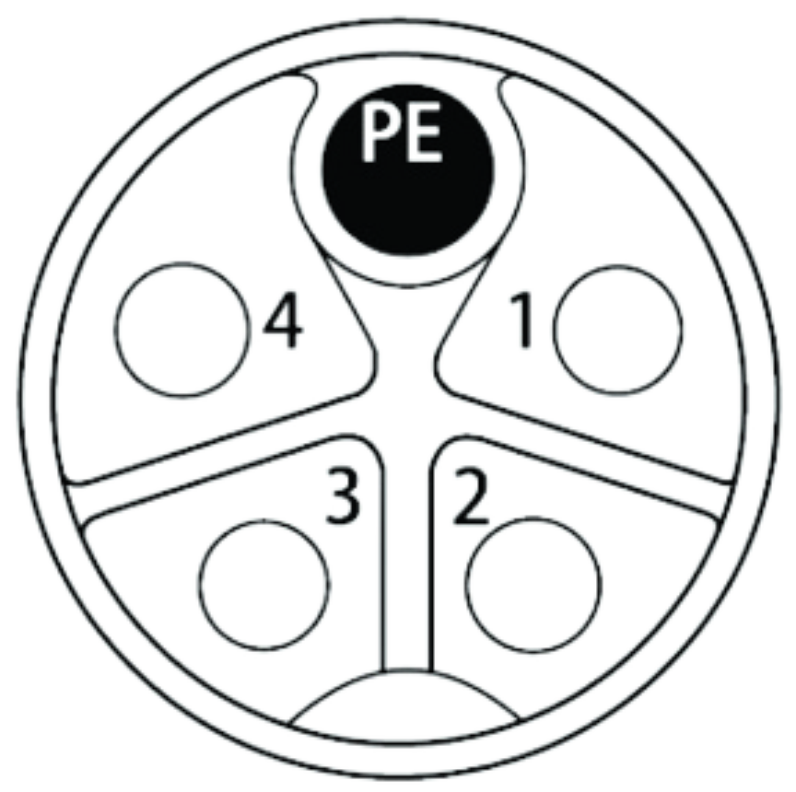
Pin-Out & Wire Colour
| Pin | Wire Color |
|---|---|
| 1 | BK |
| 2 | BK |
| 3 | BK |
| 4 | BK |
| PE | GN/YE |
Face View
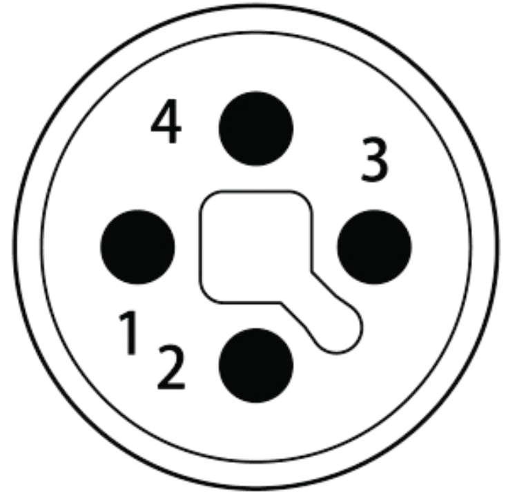
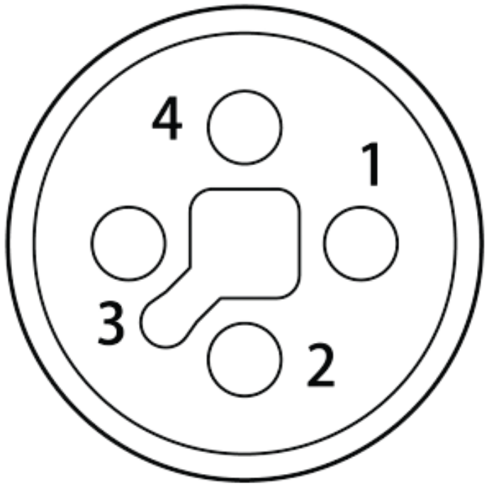
Pin-Out & Wire Colour
| Pin | Wire Color |
|---|---|
| 1 | BN |
| 2 | WH |
| 3 | BU |
| PE | BK |
Face View
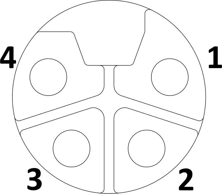
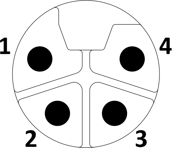
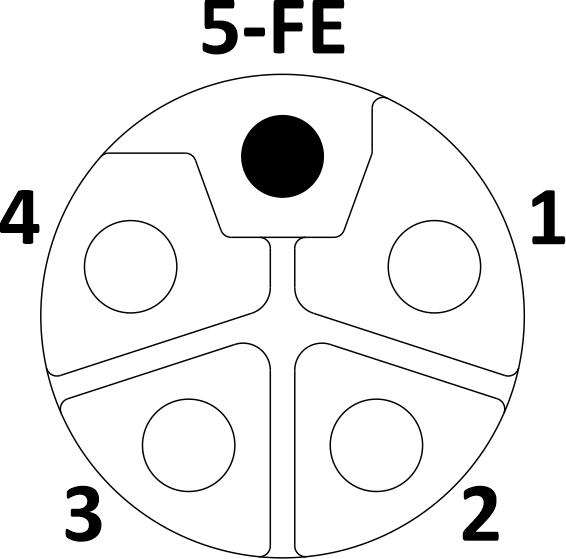
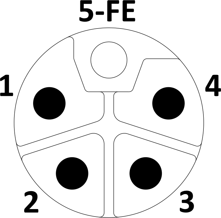
Pin-Out & Wire Colour
| Pin | 4-Pin Male/Female | 5-Pin Male/Female |
|---|---|---|
| 1 | BN | BN |
| 2 | WH | WH |
| 3 | BU | BU |
| 4 | BK | BK |
| 5 | — | GN/YE |
Pin Assignments of 7/8" Connector — European
Face View
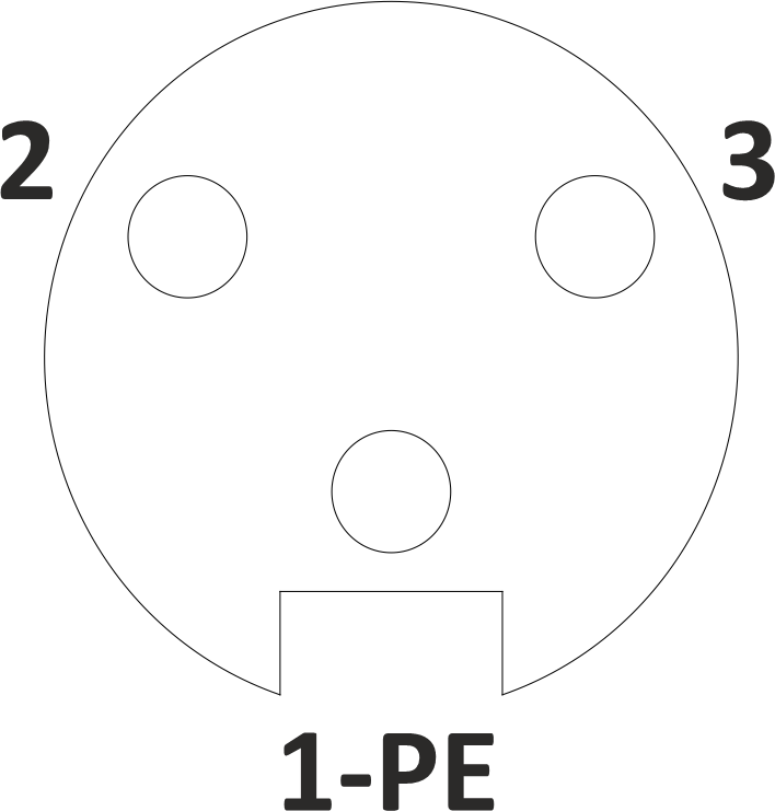
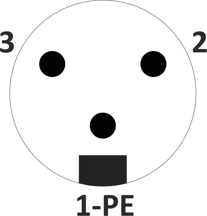
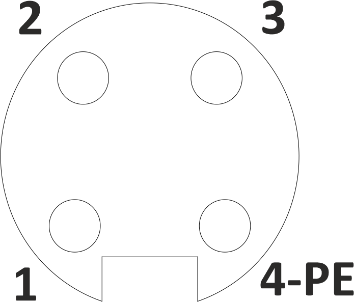
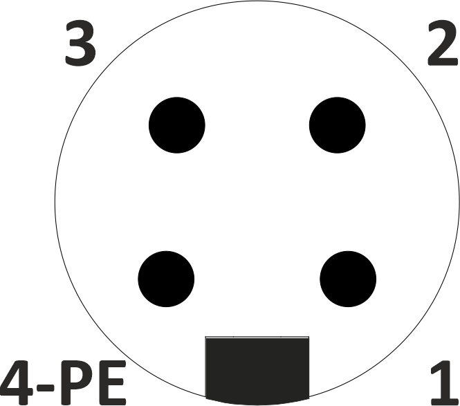
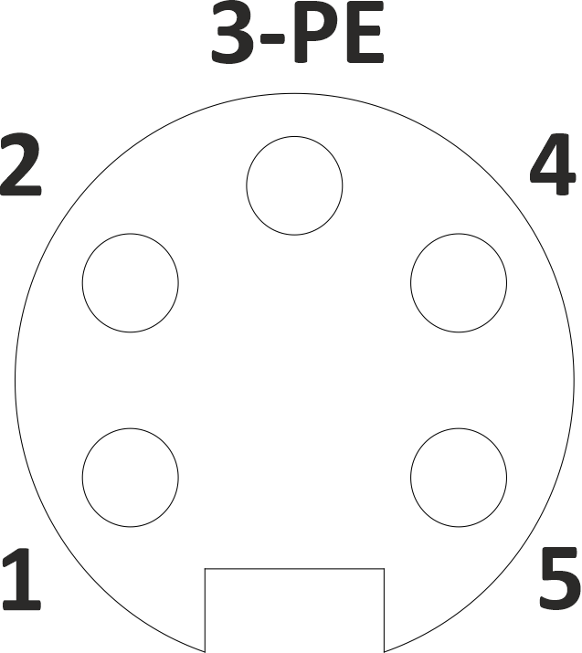
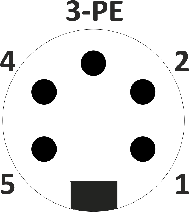
Pin-Out & Wire Colour
| Pin | 3-Pin Male/Female | 4-Pin Male/Female | 5-Pin Male/Female |
|---|---|---|---|
| 1 | GN/YE | BN | BK |
| 2 | BN | WH | BU |
| 3 | BU | BU | GN/YE |
| 4 | — | BK | BN |
| 5 | — | — | WH |
Pin Assignments of 7/8" Connector — American
Face View
Pin-Out & Wire Colour
| Pin | 3-Pin Male/Female | 4-Pin Male/Female | 5-Pin Male/Female |
|---|---|---|---|
| 1 | GN/YE | BK | WH |
| 2 | BK | WH | RD |
| 3 | WH | RD | GN/YE |
| 4 | — | GN/YE | OR |
| 5 | — | — | BK |
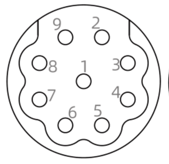
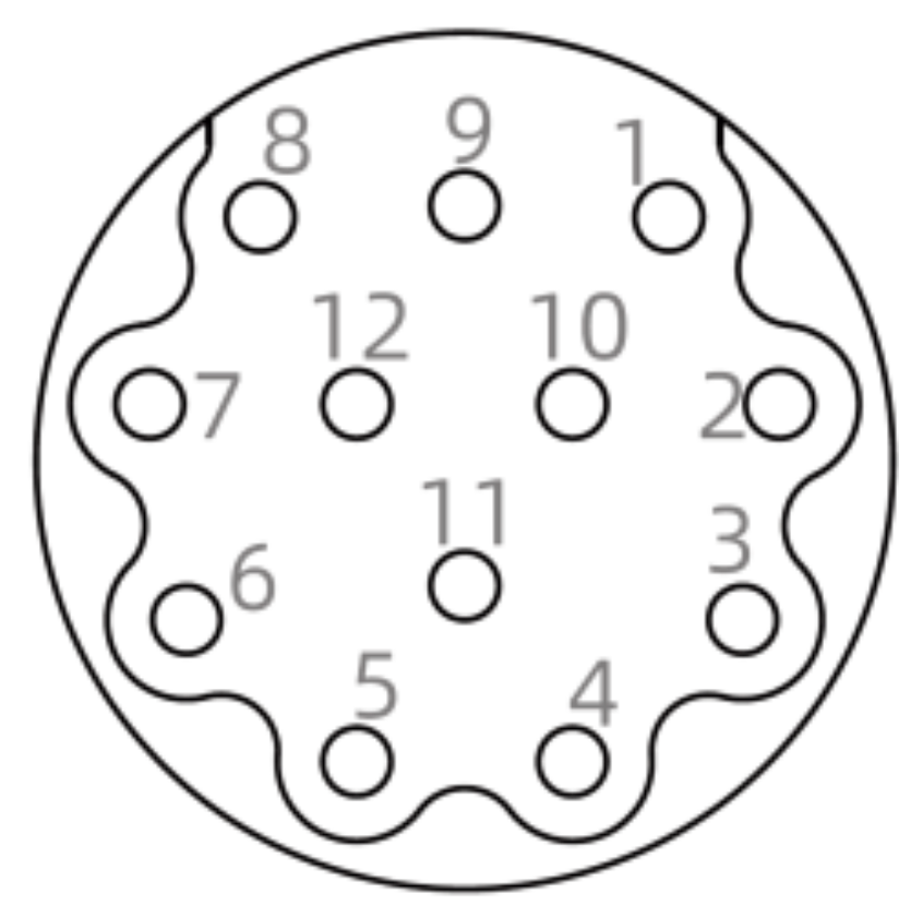
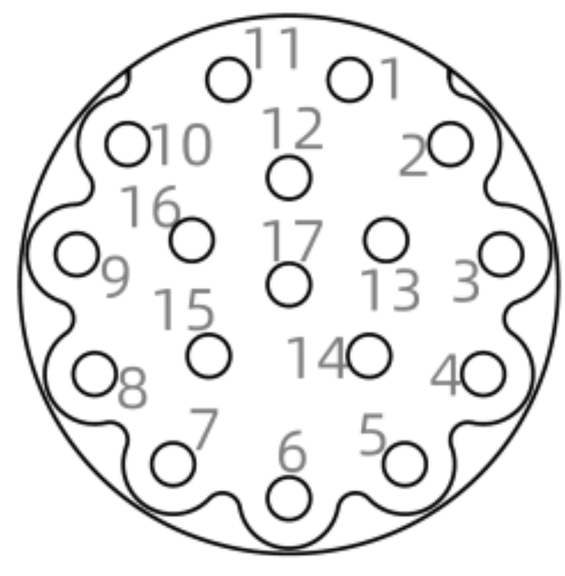
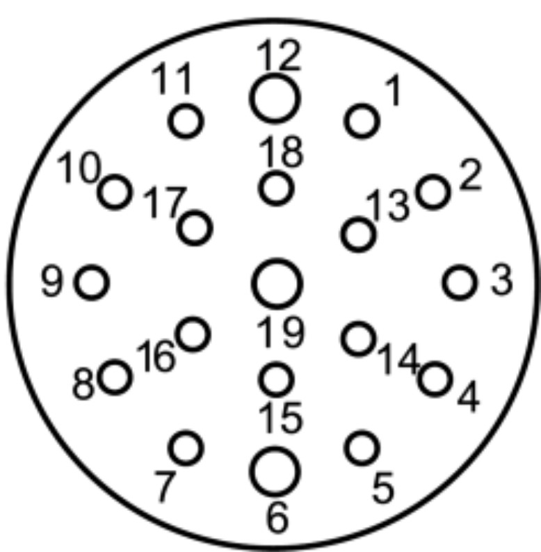
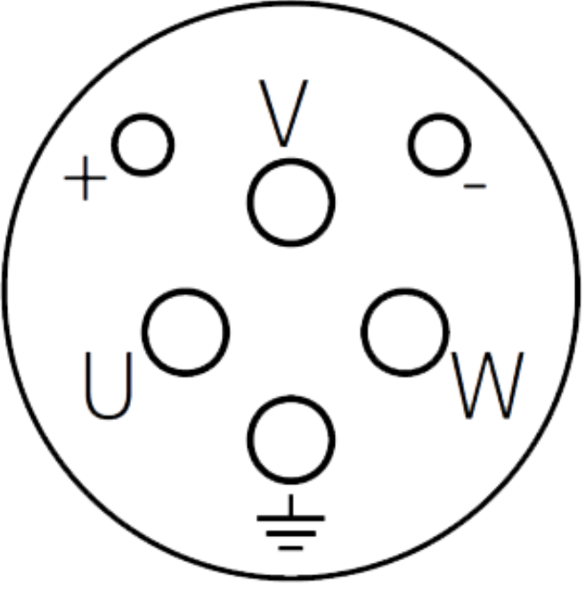
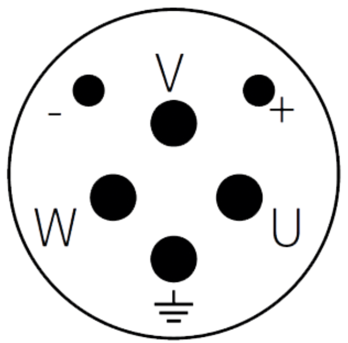
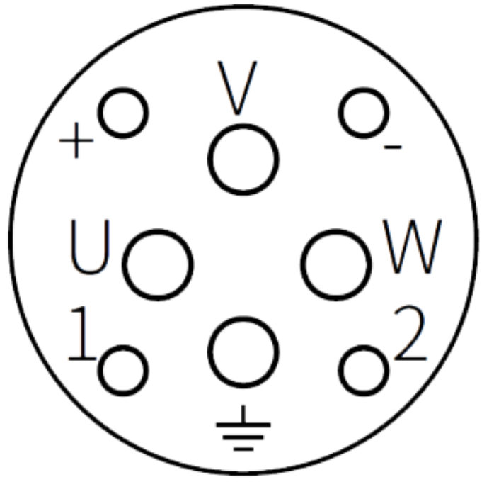
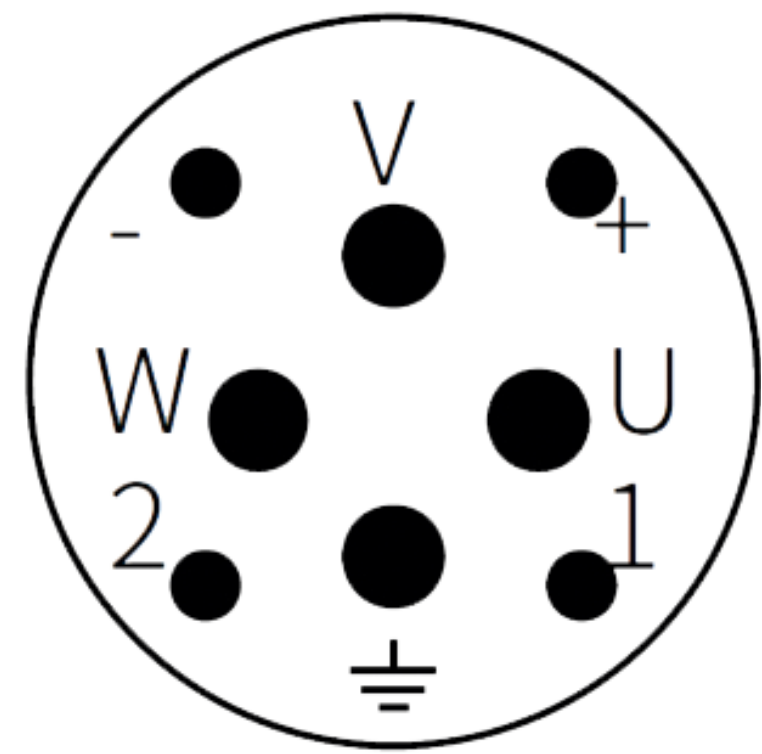
M23 P-Coded Male / Female
Face View Variants
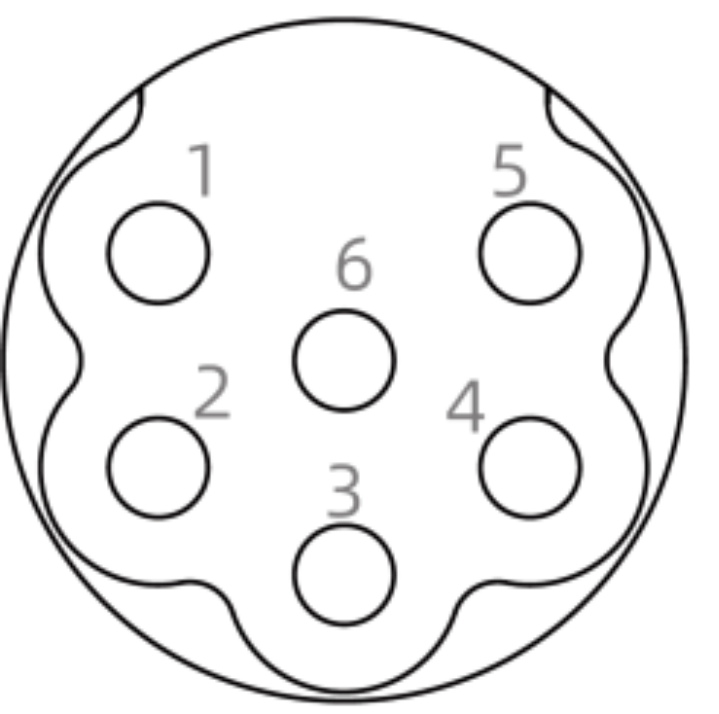
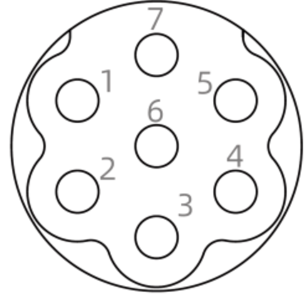
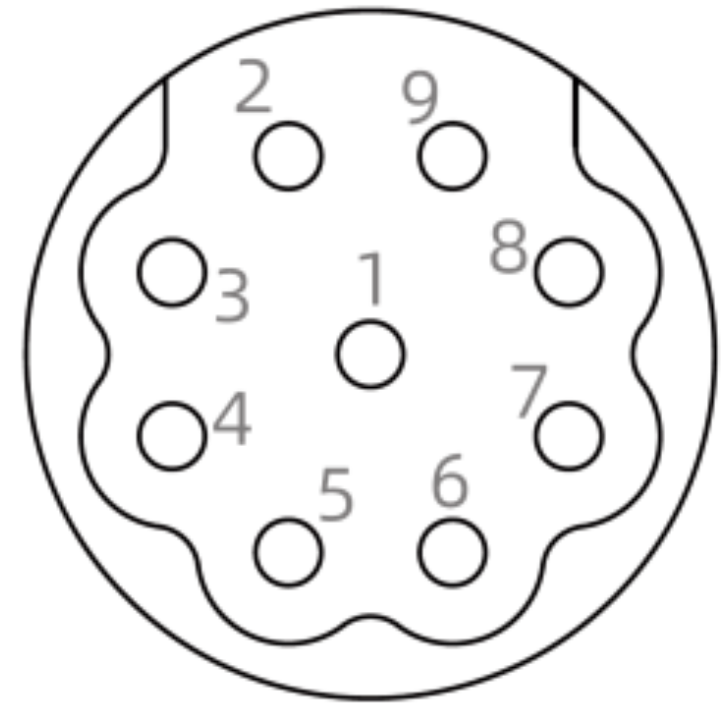
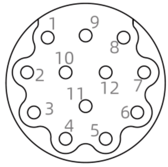
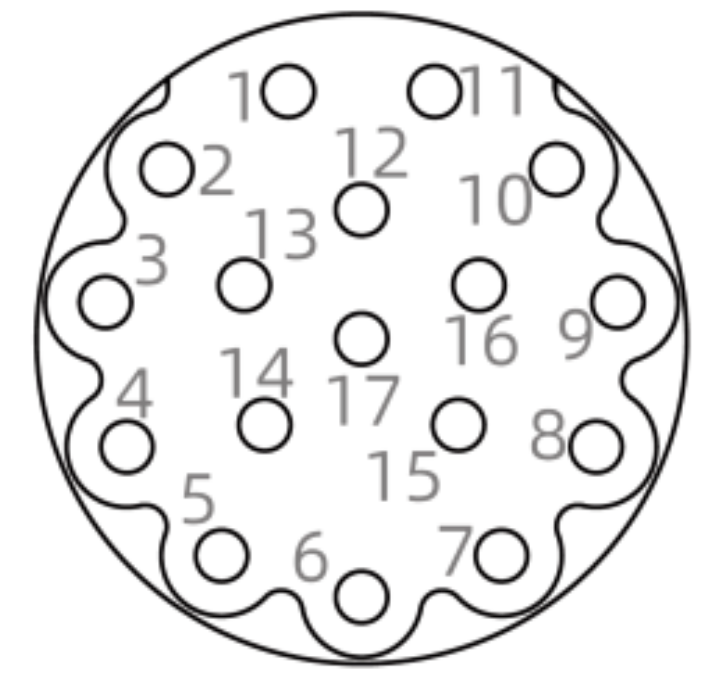
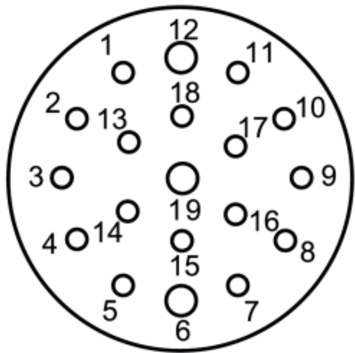
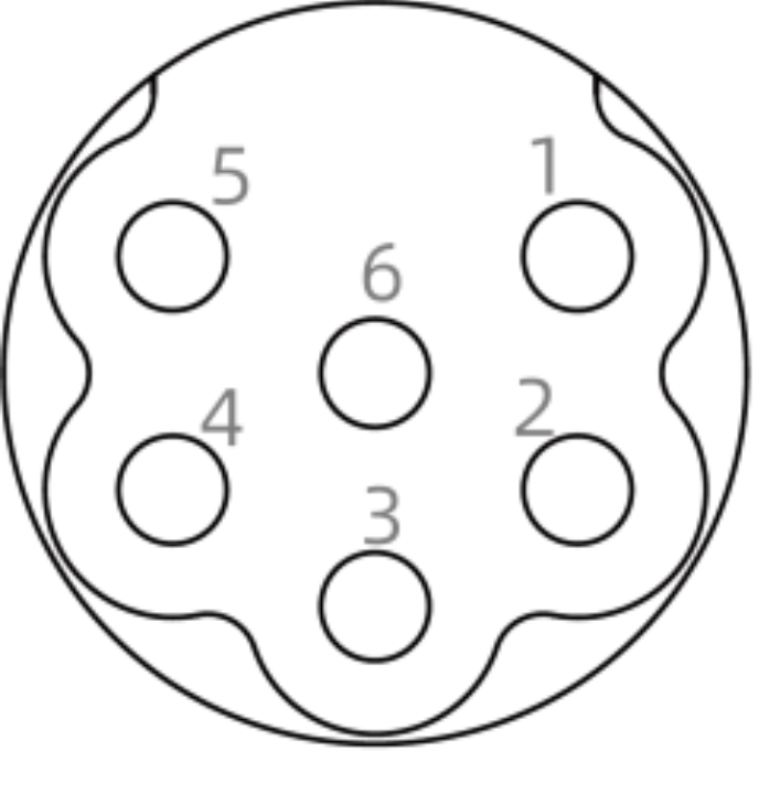
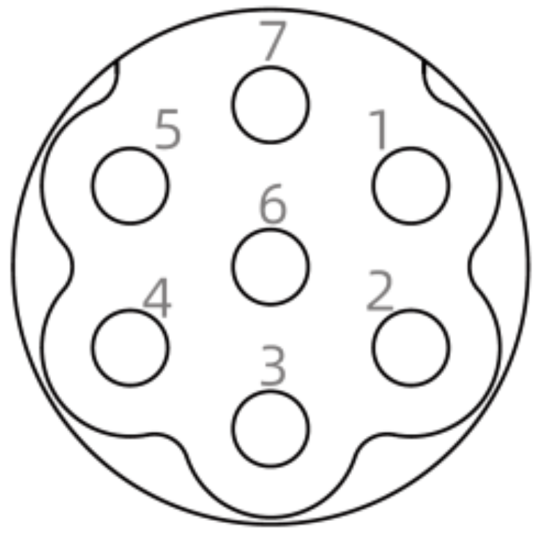
M23 E-Coded Male / Female
Face View Variants
M23 Power Male / Female
Face View Variants
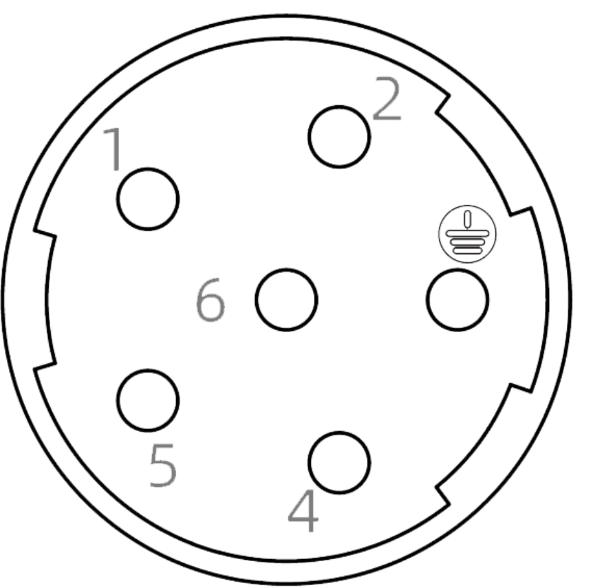
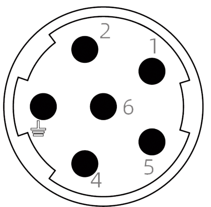
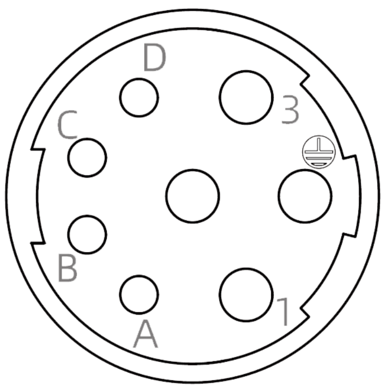
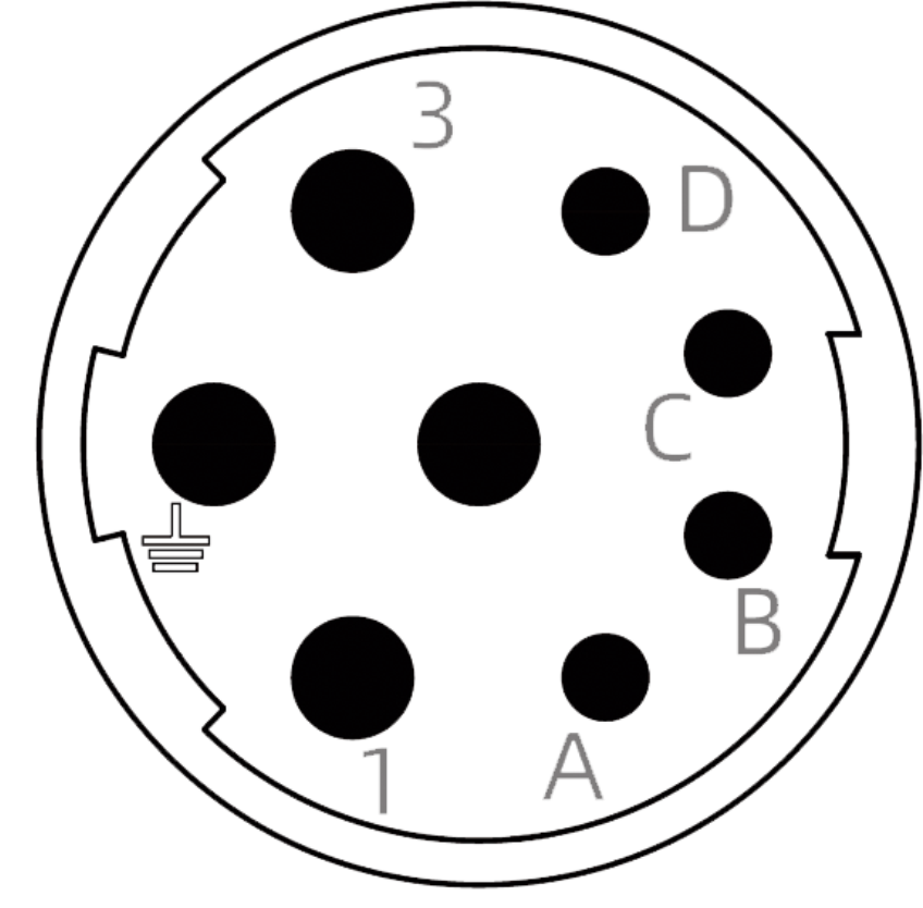
M40 Male / Female
Face View Variants
Wire Colour Legend (IEC 60757)
BK
Black
BN
Brown
WH
White
BU
Blue
GN
Green
YE
Yellow
GY
Grey
RD
Red
OR
Orange
VT
Violet
PK
Pink
GN/YE
Green/Yellow
WH/OR
White/Orange
WH/GN
White/Green
WH/BN
White/Brown
WH/BU
White/Blue
GY/PK
Grey/Pink
RD/BU
Red/Blue
SH (cable shield / drain wire) appears on shielded data lines such as M12 A-Coded CC-Link and CANopen. It is not a colour but a bare or tinned conductor bonded to the cable's foil/braid screen.